Let me start by stating that I have no formal knowledge of electronics!
This works, but if I've broken some cardinal rule of electronics, let me know and I'll update the design.
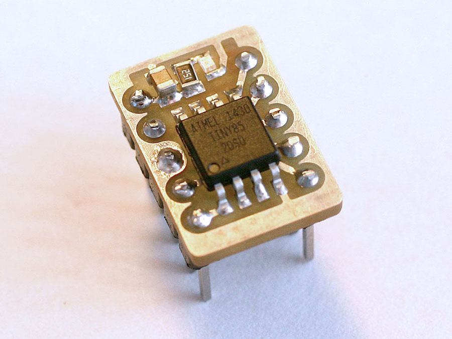
The modularity of Arduinos is great, but after playing with them for a year or so, I wanted to start building things that needed a little more integration. I also wanted to design the components and programming around the actual controller I'd be using. So, I decided to start by building a small breadboard friendly ATTiny85.
A project I've been thinking about will require interfacing with a Bosch BMP280 pressure sensor and controlling a standard servo. So I decided to power the Tiny85 with a 3.3 volt regulator so I wouldn't have to do any level translation between it and the BMP280, and also add a 5 volt regulator to power the servo. The 3.3 volt regulator can supply 80 mA, which should be more than enough for the Tiny85, the BMP280 and a few other odds and ends. The 5V regulator can supply 250 mA which should be plenty for the micro servo I intend to use, which I measured at around 80 mA under typical operation. Once I have everything working on the breadboard, I can simply extend the circut to integrate the pressure sensor and other components and cut a new PC board.
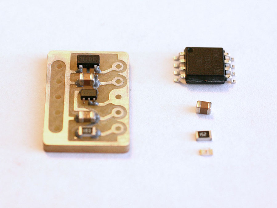
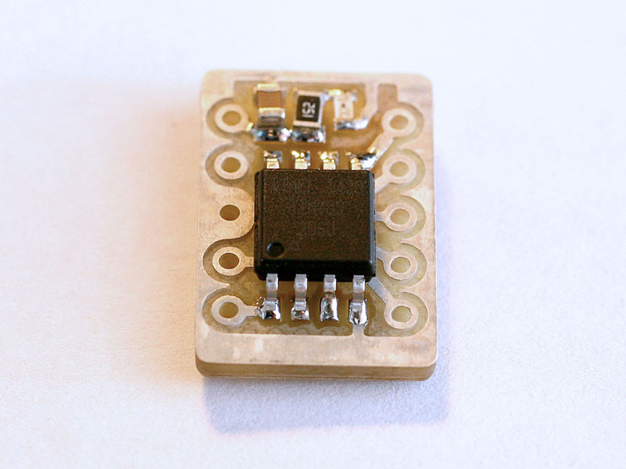
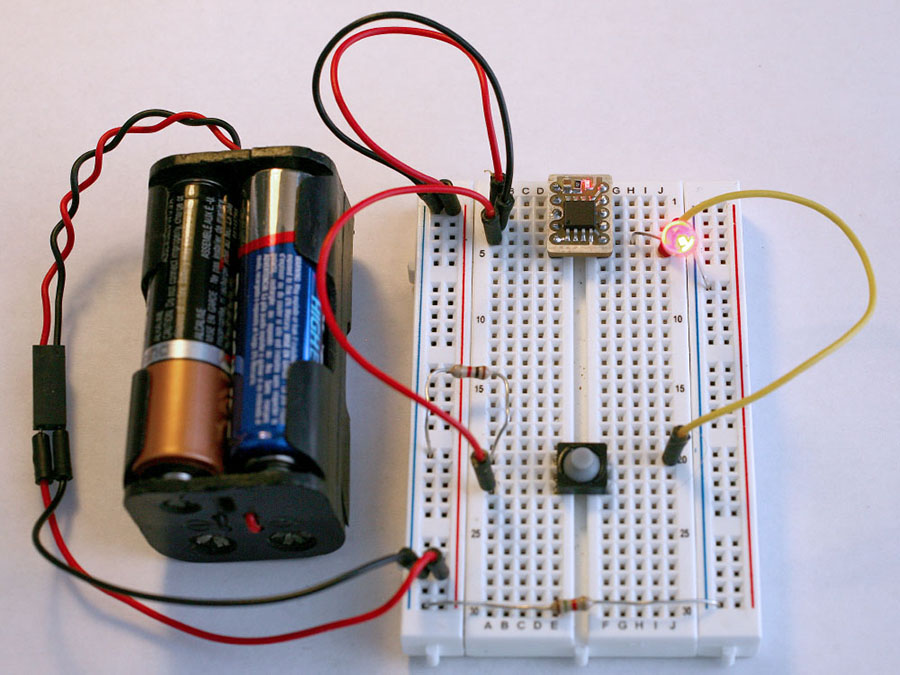
I added a small status LED just to indicate that the board was receiving power, but this could easily be omitted. Outside that, it just consists of a few smoothing capacitors and a resistor to pull up the reset pin on the Tiny85.
The capacitor and resistor values were chosen based on data sheet schematics and those I've seen used in other Tiny85 based boards, as I assume they know what they're doing far more than I do!
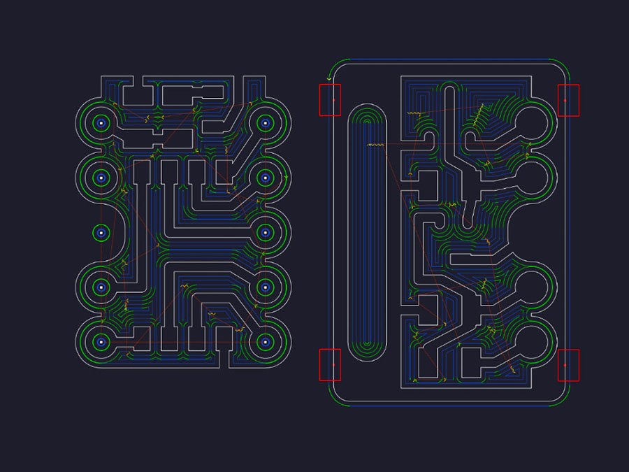
As I said, I don't know much about electronics, and my admitedly too-short attempt to learn Eagle sent me running to what I already know - Adobe Illustrator! Not an appropriate circuit design application by any stretch of the imagination, but like my little microcontroller itself, all I can say is... it works!
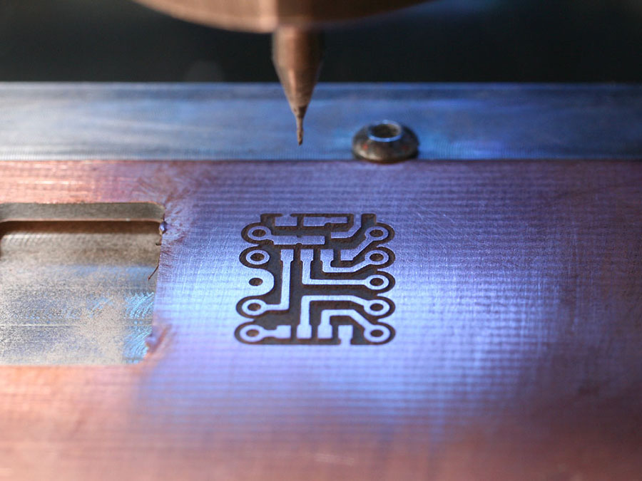
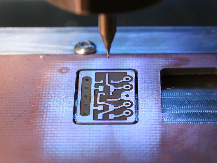
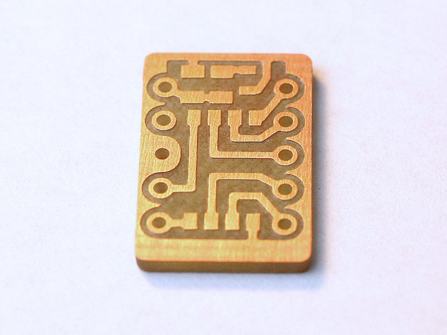
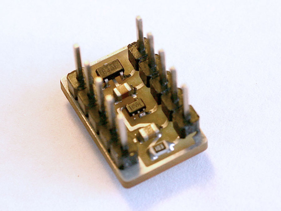
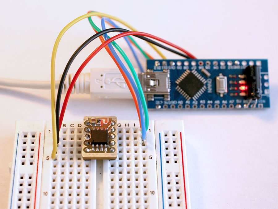
As they say, a picture is worth a thousand words, so instead of boaring everyone to death, I just documented the steps with photographs.
If you have any questions or comments, feel free to e-mail me.
|
|
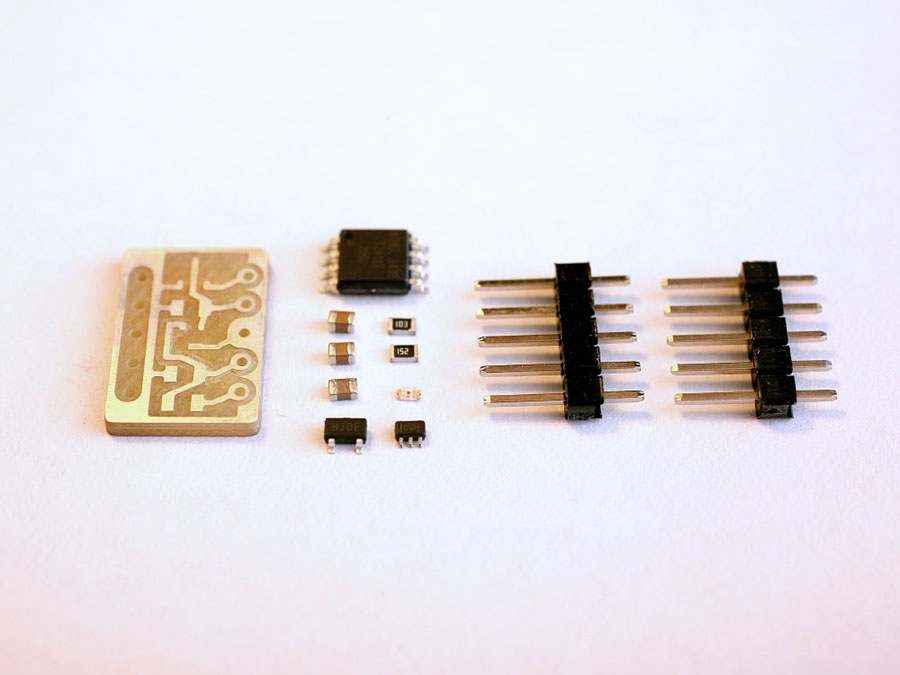
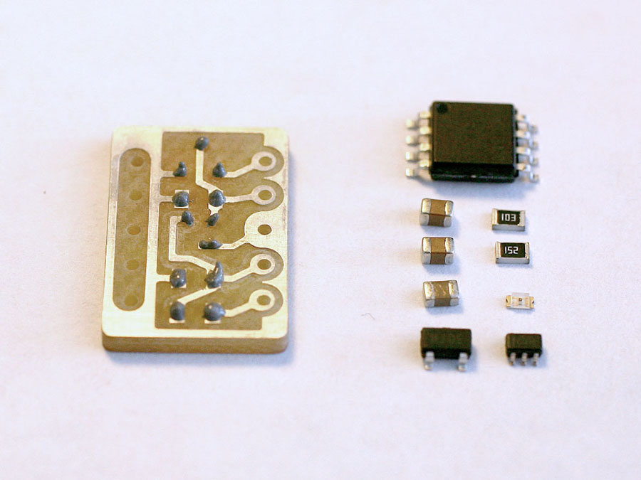
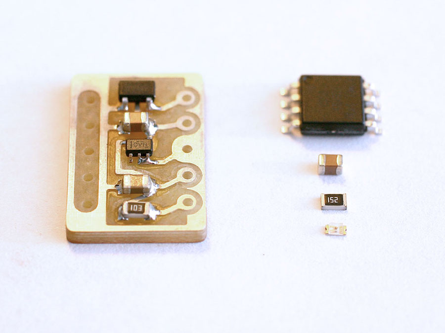
Parts list:
ATTiny85
5 Volt Regulator
3.3 Volt Regulator
SMD LED
SMD 1.5 and 10k resistors
SMD 1uf and 22uf capacitors
Misc building supplies (PC board, solder, CNC milling machine, etc.)
Files:
DXF Outlines
|
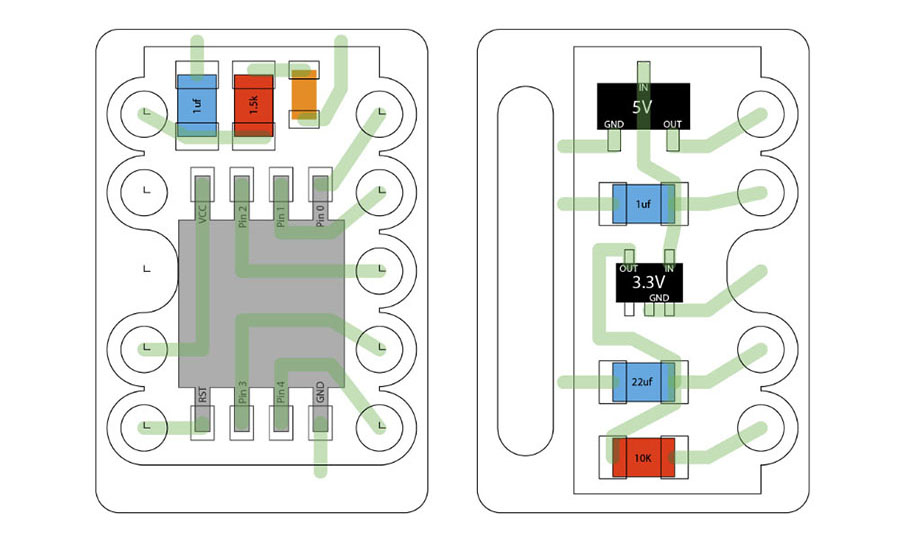
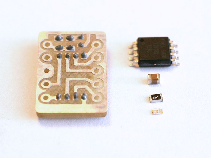
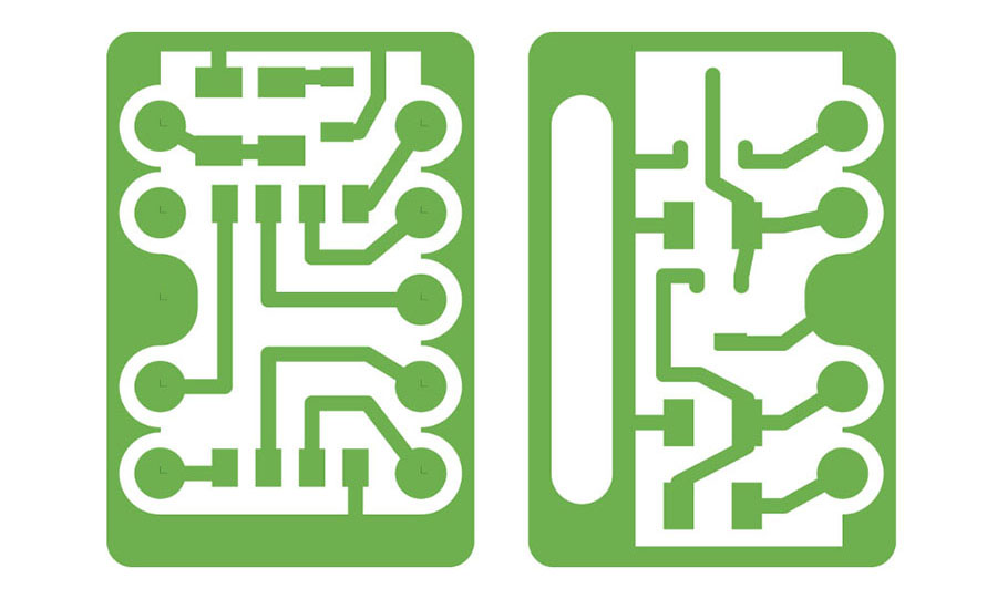 Once the circuit was laid out, I combined all the paths and shapes into contiguous outlines.